
POWERSCADA
Communication: One System, Many Devices
PowerScada brings multi-brand, multi-protocol PLCs, power meters and building equipment into one system. Everything is configured in a four-level structure of channels, devices, register tables and tags; every tag read goes into the same cache and is then pushed to screens, alarms, trends and scripts.
Besides reading devices as a client, it can also act as a server: a Modbus TCP slave and an OPC UA server let a BMS, MES or supervisory SCADA read field data directly, with no extra gateway layer.
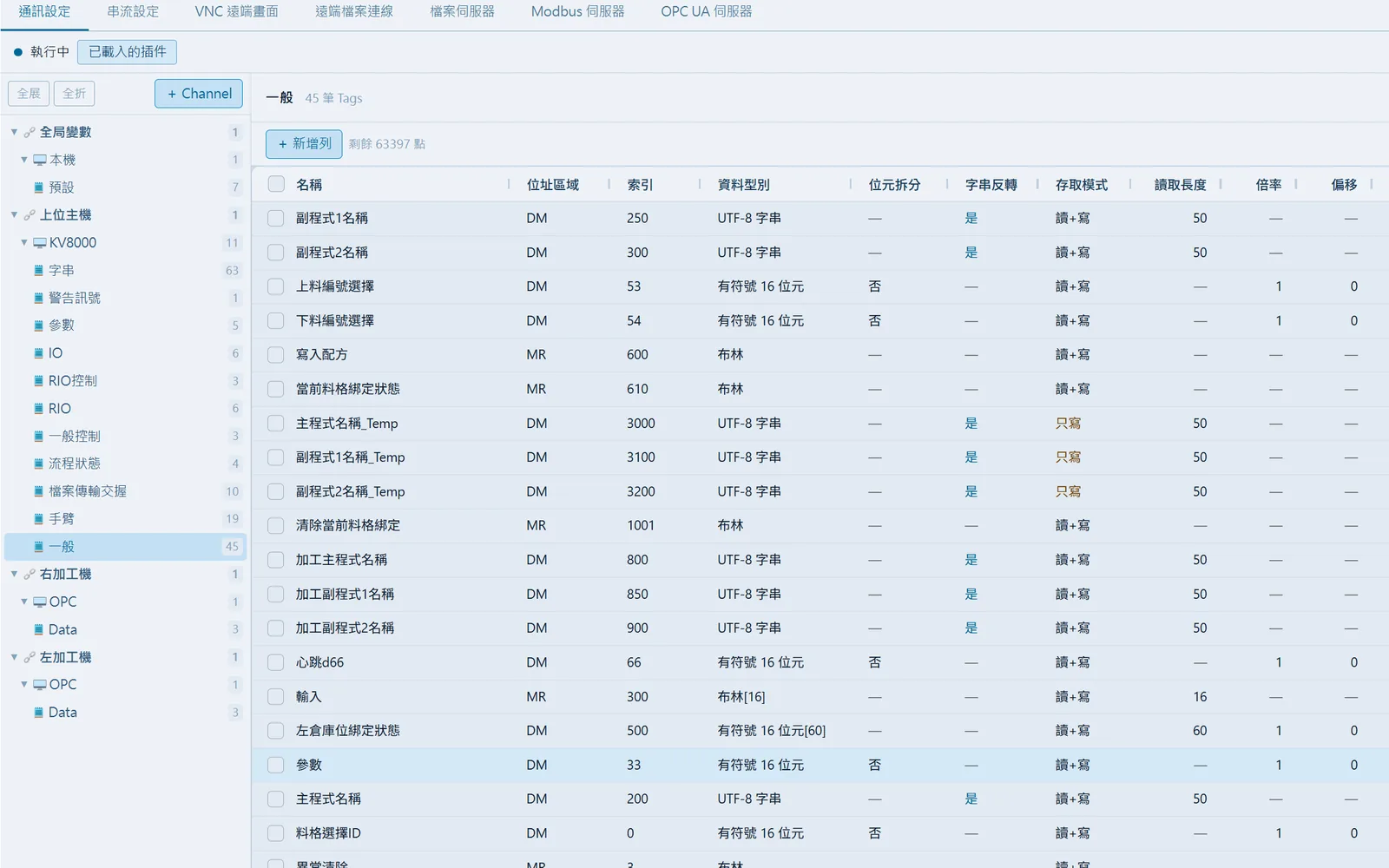
Supported protocols and models
All drivers are built in; devices can be connected as soon as installation is complete, with no communication modules to buy.
- Modbus TCP and Modbus RTU (RS-232/RS-485).
- Mitsubishi MC 3E Binary (FX5U, Q and iQ-R series); Mitsubishi FX2N/FX3U programming port (RS-422, SC-09 cable required) and a TCP version bridged through a serial device server.
- KEYENCE KV-3000, KV-5000, KV-7000 and KV-8000 (Host-Link).
- Vigor VS (TCP/RTU) and M/VB/VH series (RTU).
- Delta DVP-ES2 and DVP-SE (RTU and TCP, addressed by the vendor's own device names); FATEK FB series (serial).
- BACnet/IP and BACnet MS/TP (RS-485), with device scanning and point scanning.
- OPC UA client: connects to Kepware, Siemens, Beckhoff and other servers, with polling or subscription mode selectable per table.
Acting as a server for supervisory systems
The Modbus TCP server supports function codes 01, 02, 03, 04, 05, 06, 15 and 16 with multiple requests in parallel on one connection, and offers a station number mode, read-only mode, a maximum connection count and an IP whitelist. The OPC UA server provides read, write and subscribe, with both an unencrypted and a Basic256Sha256 endpoint, and supports username/password and certificate trust management. Up to 10 servers of each kind per project.
No need to type tags one by one
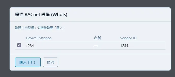
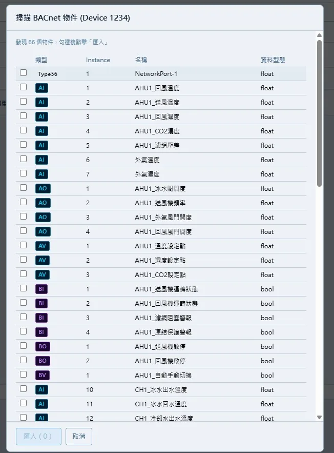
BACnet/IP scans devices by broadcast and lists them all in about 10 seconds; import with one click, then scan that device's AI, AO, AV, BI, BO, BV, MI, MO and MV objects and tick the ones to import. OPC UA browses nodes in a tree and lets you tick variables, without stopping the runtime.
- Bulk creation: set the address step (for example a step of 3 produces DM0, DM3, DM6), the access mode and the string length.
- Excel import and export: export the whole communication table to xlsx in one click; import checks every row and lists the row numbers and reasons for any errors. You can also copy and paste straight from Excel.
- Bit splitting: a 16-bit tag can be split into .0 to .15 and each bit bound to indicator lights, buttons, alarms and trends; on write the system reads, modifies and writes back the whole word automatically, and the license still counts it as 1 tag.
- Array tags: length 1 to 1024; components can bind a single element, and scripts can write the whole array or a single element.
- Scale and offset: displayed value = raw value × Scale + Offset, inverted automatically on write; byte orders ABCD, DCBA, BADC and CDAB are set at the channel level.
- Live address validation: range, multiple and base are checked against each model's address specification; X/Y on Mitsubishi FX and Vigor are entered in octal, and out-of-range addresses are rejected with an explanation.
Stability and troubleshooting tools
On deployment every channel connects at the same time; offline devices are still monitored and reconnected automatically in the background, and reading resumes as soon as they come back. Adjacent tags are merged automatically into contiguous read blocks to reduce round trips.
- Communication test: send custom hexadecimal raw data on a running network or serial channel and see the response, with an optional automatic Modbus RTU CRC, as often as every 0.1 seconds.
- Pass-through tool: lets the PLC vendor's software or a Modbus tool reach field devices through the SCADA host, with exactly the same addresses and ports as on site; up to 5 at a time.
- Each tag can be read/write, read-only or write-only; write-only tags are left out of polling entirely.
- Global variables: in-memory variables that are not polled from the PLC, can be persisted, and are available to scripts, screens and the Modbus server.
Screenshots
How to set it up
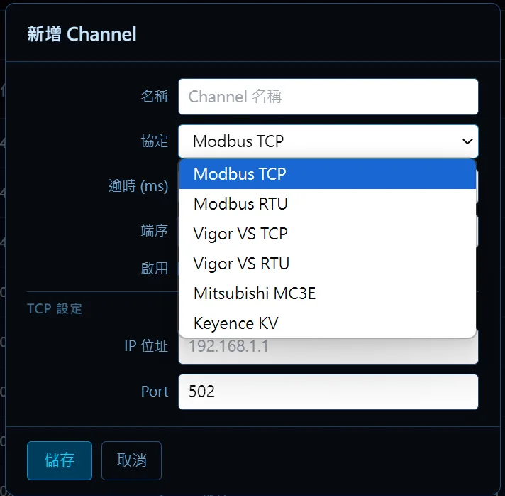
- 1Open "Device communication" from the editor toolbar and add a channel: choose the protocol and enter the IP and port, or the COM port, baud rate, data bits, parity and stop bits, plus the timeout and byte order.
- 2Add a device under the channel and enter the station number (Modbus 1 to 247), the BACnet Device Instance, or the OPC UA connection details.
- 3Add a register table and set the scan period (typically 1000 ms, recommended minimum 200 ms).
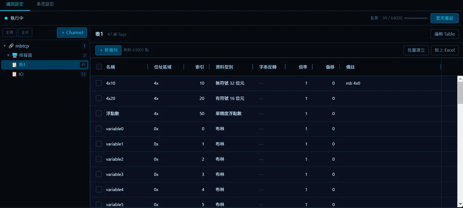
- 4Create tags by typing them in, bulk creation, pasting, importing from Excel, or scanning and browsing for BACnet and OPC UA; set the data type, scale and offset, unit, bit splitting or array length.
- 5Save, then deploy or click "Restart communication" to apply the settings.
- 6Use "Communication test" to troubleshoot wiring or station numbers; use the pass-through tool when you need the vendor's software to upload or download the PLC program.
- 7To let a supervisory system read the data, go to the "Modbus server" or "OPC UA server" tab, add a server and publish tables.
FAQ
FAQ
How do I bring in the tags from a BACnet device?
Create a BACnet/IP or MS/TP channel, stop the runtime, click "Scan devices" and tick the devices to import; then click "Scan tags" to list every object on that device and tick the ones to import. Data types are mapped automatically (AI/AO/AV to float, BI/BO/BV to Boolean, MI/MO/MV to integer).
Does an offline device slow down the whole deployment?
No. Every channel connects at the same time; offline devices are still monitored and the system reconnects them automatically in the background, resuming reads as soon as they come back.
How do I use a 16-bit status word in the PLC as 16 switches?
Tick "Bit splitting" for that tag in the communication table. Indicator lights, buttons, alarms and trends can then bind single bits .0 to .15; on write the system reads, modifies and writes back the whole word automatically, and the license still counts the split tag as 1 tag.